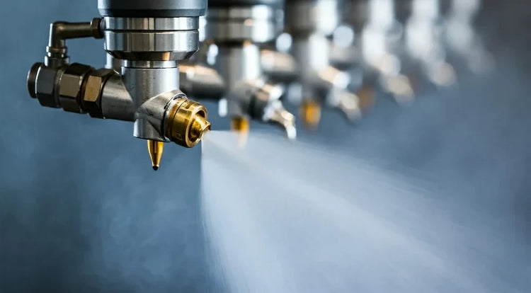
Paper Machine Shower Nozzles
High-pressure needle shower nozzles (40â80 bar) for felt conditioning and cleaning, low-pressure lubrication shower nozzles for wire and felt surface management, trim squirt nozzles for sheet edge cutting, edge moistening spray nozzles, and forming fabric shower bars â flat-fan and full-cone nozzles in tungsten carbide construction for continuous operation on fourdrinier, twin-wire, and tissue machine forming and press sections
Paper machine shower nozzles are not interchangeable components â they are precision elements in the sheet formation and press dewatering system where the wrong nozzle in the wrong position produces measurable consequences at the reel. A high-pressure felt cleaning nozzle traversing at incorrect oscillation speed relative to machine speed creates permanent groove wear tracks in the felt needling that reduce felt service life by 30â50% and increase press section energy consumption. A trim squirt nozzle with 5% excess flow produces a sheet edge that is wider than intended, wastes fiber, and creates a reel spool with mismatched edge densities that triggers splice failures in converting. A wire lubrication shower running at double the design flow rate produces a wet wire section that increases vacuum energy demand and can cause sheet formation problems in the first drainage elements.
NozzlePro supplies shower nozzles for every paper machine position â high-pressure flat-fan needle nozzles for felt conditioning and cleaning, TC-insert flat-fan shower bar nozzles for wire and felt low-pressure showers, precision trim squirt nozzles for hydraulic sheet edge cutting, edge moistening nozzles for cross-direction moisture profile control, and roll lubrication dosing nozzles. All positions in TC orifice insert construction for continuous white water service. ISO 9001 certified manufacturing with ±1% orifice flow verification on all shower bar replacement sets.
Paper machine shower nozzles cover five distinct application types, each with different pressure, angle, and material requirements: high-pressure needle showers use narrow-angle flat-fan nozzles (15°â25°, 40â80 bar) in oscillating shower arms for felt conditioning, permeability restoration, and high-pressure wire cleaning â needle shower oscillation speed must be calculated from machine speed and nozzle angle to achieve the correct cleaning band overlap without felt groove wear; low-pressure lubrication and conditioning showers use flat-fan nozzles (65°â110°, 0.5â3 bar) in stationary shower bars for wire surface lubrication, felt surface wetting, and suction box cover lubrication â flow rates precisely controlled to avoid over-wetting that increases vacuum energy demand; trim squirt nozzles use solid-stream or very narrow-angle flat-fan nozzles (0°â10°, 15â40 bar) positioned at the sheet edge to hydraulically cut and define the trim strip â nozzle position and flow rate set by the target sheet width, not by a fixed specification; edge cutting and moistening spray nozzles use flat-fan nozzles (15°â30°, 2â10 bar) for cross-direction moisture profile edge correction and for sheet edge conditioning in the press section; and forming fabric shower bars use flat-fan nozzles (25°â50° oscillating, 65°â80° stationary) across the full machine width for wire cleaning, lubricating, and forming control. Tungsten carbide orifice inserts are the minimum specification for all positions â paper machine white water carries calcium carbonate, kaolin, and titanium dioxide fillers that erode standard stainless orifices within 2â4 weeks at shower bar pressures.
Paper Machine Shower Nozzle Collections
Shop by position or nozzle type
Paper Machine Shower Applications
Every shower position from forming fabric through press section â nozzle type, operating requirements, and the process consequence of getting it wrong
High-Pressure Needle Shower Nozzles
Narrow-angle flat-fan nozzles (15°â25° spray angle, 40â80 bar) in oscillating shower arms deliver concentrated high-pressure cleaning jets across the full felt width on press section felts (wet felts, pickup felts, transfer felts) and on forming fabric cleaning positions. The "needle shower" designation refers to the narrow flat-fan pattern â at 15°â25° and 40â80 bar, the jet is narrow enough to function as a high-energy hydraulic needle that penetrates felt needling layers and dislodges filler particles, fiber fines, pitch deposits, and sizing materials that progressively reduce felt permeability. Permeability loss is the primary cause of press section moisture profile deterioration and increased press nip pressure requirements â a felt with 20% permeability reduction produces proportionally higher moisture content in the pressed sheet, increasing dryer steam demand. Nozzle performance at 40â80 bar depends on orifice geometry maintaining the rated flow and spray angle throughout the service interval â TC inserts at 1,400â1,800 HV maintain consistent orifice dimensions against the calcareous white water present at most paper machine press shower positions. The critical companion specification to nozzle selection is oscillation speed â see the selection principles section for the oscillation calculation.
High-Pressure NozzlesLow-Pressure Lubrication & Conditioning Shower Nozzles
Wide-angle flat-fan nozzles (65°â110° spray angle, 0.5â3 bar) in stationary shower bars provide continuous surface lubrication and moisture conditioning across the full width of forming fabrics, press felts, and suction box covers. Lubrication showers on the wire section reduce wire-to-table board and drainage element friction, extend wire service life, and maintain the hydrodynamic film that supports even drainage in the forming zone. The flow rate specification for wire lubrication showers is not arbitrary â it is calculated from wire speed, contact area with drainage elements, and the minimum film thickness required to prevent boundary contact. Over-specification (excess flow) increases vacuum energy consumption because the additional water must be removed by the vacuum system; under-specification allows wire-to-table contact that increases wire wear and can produce formation streaks from uneven drainage. Felt conditioning showers (0.5â2 bar) on press felts maintain uniform felt moisture content across the machine width between high-pressure cleaning cycles, preventing the dry-edge degradation that develops when felt edges receive less conditioning than the center. Suction box cover lubrication nozzles apply a controlled water film to suction box cover plates, reducing friction between the moving felt and stationary box top â insufficient lubrication here causes cover wear and felt damage at the suction slot edges.
Flat-Fan NozzlesTrim Squirt Nozzles
Solid-stream or very narrow-angle flat-fan nozzles (0°â10°, 15â40 bar) positioned at the sheet edge hydraulically cut the trim strip from the main sheet web, defining the finished sheet width with a clean, consistent edge. The trim squirt nozzle is positioned perpendicular to the machine direction at the edge of the target sheet width â the high-velocity water jet cuts through the wet fiber sheet on the forming fabric and creates a narrow trim strip (typically 30â80 mm wide) that is stripped from the wire edge and directed to the broke collection system. Trim squirt nozzle specification is determined by three variables: machine speed (higher speed requires higher flow rate to maintain a continuous cut through the sheet), furnish consistency and sheet basis weight (heavier sheets require higher pressure), and trim strip width (narrower trim requires more precise nozzle positioning and tighter jet geometry). Solid-stream nozzles produce the cleanest hydraulic cut for trim squirts because the coherent water column maintains maximum cutting velocity at the sheet surface â flat-fan nozzles introduce spray distribution that can produce a ragged edge rather than a clean cut. Positioning accuracy matters: a trim squirt nozzle misaligned 5 mm from the target sheet width produces a sheet 5 mm wider or narrower than specification, which compounds across a reel into significant width variation.
Solid-Stream NozzlesEdge Cutting & Sheet Edge Moistening Nozzles
Flat-fan nozzles (15°â30°, 2â10 bar) positioned at the sheet edge for two distinct functions: hydraulic edge cutting in press and coater sections, and cross-direction moisture profile correction at the sheet edge. Edge cutting in the press section uses water jets to cut cleanly through the pressed sheet before it enters reel winders or converting equipment â maintaining consistent sheet width through the press section without mechanical slitting at wet press moisture levels. Sheet edge moistening corrects the common paper machine problem of over-dried sheet edges: forming fabric edges drain faster than the center (more vacuum exposure per unit width), producing edges that arrive at the press section and dryer section drier than the sheet center. Left uncorrected, this cross-direction moisture profile variation causes differential shrinkage across the sheet width, producing tension variation, edge cracking, and reel tightness variation that causes winding defects. Edge moistening nozzles apply a precisely controlled fine water spray to the sheet edges in the wire or press section to equalize moisture content before the dryer section â the flow rate must be calibrated by measurement of the actual sheet moisture profile, not by a fixed specification.
Flat-Fan NozzlesForming Fabric (Wire) Shower Bars
Flat-fan nozzles across the full machine width in both oscillating (25°â50°, 5â25 bar for cleaning) and stationary (65°â80°, 0.5â3 bar for lubrication) shower bars maintain forming fabric cleanliness, drainage performance, and surface condition on fourdrinier, hybrid former, and gap former machines. Forming fabric shower bars operate in the highest-filler-concentration zone of the paper machine â the wire pit white water carries the full filler load of the furnish, typically 15â40% calcium carbonate or kaolin by mass, at concentrations that make TC orifice inserts mandatory for any service interval beyond four weeks. Stationary wire shower bar nozzle spacing is calculated to provide 100â150% overlap at the wire surface â gaps between adjacent nozzle coverage zones create dry lanes that accumulate filler and fine content, progressively reducing drainage and producing formation streaks visible in the finished sheet. The high-pressure wire cleaning shower (oscillating, 15°â25°, 40â60 bar) operates on the return run of the wire, below the forming table â its position on the wire underside allows the high-pressure jet to penetrate and flush the wire mesh from the inside surface, dislodging the filler and fiber mat that builds up on the drainage side.
Flat-Fan NozzlesPress Roll Cleaning & Uhle Box Showers
High-impact flat-fan nozzles (15°â25°, 25â60 bar) for press roll surface cleaning, and flat-fan shower bars (0.5â2 bar) for uhle box suction slot cover lubrication and cleaning on press section suction pressure rolls. Press roll cleaning showers remove the fiber and filler deposits that accumulate on press roll surfaces during operation â particularly on granite, synthetic, and polyurethane-covered press rolls where surface roughness changes affect nip pressure distribution and sheet picking tendency. The shower jet must be directed tangentially to the roll surface at the point where the felt separates from the roll after the nip, where deposit accumulation is highest and where the high-pressure jet can penetrate between roll surface and felt rather than impacting the felt surface directly. Uhle box cover plate lubrication showers maintain the water film between the moving felt and the stationary uhle box top plate â the felt runs over the suction slot of the uhle box at high speed and the friction between felt and cover plate generates significant heat at the slot edge. Insufficient lubrication at this position causes cover plate wear, felt bottom-surface damage, and in severe cases, hot spots at the slot edge that can damage felt structure permanently. TC inserts required for all press section shower positions â press section white water and filled furnish carry the highest filler loadings on the machine.
High-Pressure NozzlesPaper Machine Shower Nozzle Reference Table
Recommended nozzle type, pressure, spray angle, material, and critical design notes by machine position
| Machine Position | Nozzle Type | Pressure | Spray Angle | Material | Critical Design Note |
|---|---|---|---|---|---|
| Felt â High-Pressure Needle Shower | Oscillating Flat-Fan HP | 40â80 bar | 15°â25° | 316L SS body; TC orifice insert; PTFE seals | Oscillation speed calculated from machine speed, nozzle angle, and standoff â too slow creates groove wear tracks; too fast leaves dry strips. Re-verify after every machine speed change. |
| Felt â Conditioning / Low-Pressure Shower | Stationary Flat-Fan | 0.5â2 bar | 65°â80° | 316L SS or HDPE body; TC insert for white water supply | Full felt width coverage with 100â150% overlap; flow rate calibrated to maintain target felt moisture â excess flow increases vacuum energy demand at suction boxes and uhle boxes |
| Wire â High-Pressure Cleaning Shower | Oscillating Flat-Fan HP | 40â60 bar | 15°â25° | 316L SS body; TC insert; EPDM or PTFE seals | Positioned on wire return run (underside); jet penetrates wire mesh from drainage side to flush filler and fiber mat; oscillation must cover full wire width; TC insert mandatory â wire pit white water carries 15â40% filler loading |
| Wire â Lubrication Shower | Stationary Flat-Fan | 0.5â1.5 bar | 65°â110° | 316L SS or HDPE body; TC insert | Flow calculated from wire speed and drainage element contact length â over-flow increases vacuum demand; under-flow allows boundary contact causing wire wear and formation streaks; loop-return header feed to equalize pressure across all positions |
| Trim Squirt â Sheet Width Cutting | Solid-Stream or Narrow Flat-Fan | 15â40 bar | 0°â10° | 316L SS body; TC insert; precision-bore orifice | Solid-stream produces cleaner hydraulic cut than flat-fan; position set to target sheet width â 5 mm misalignment = 5 mm sheet width error; flow rate increases with machine speed and basis weight; verify trim strip integrity at all speed settings |
| Edge Moistening â Sheet Edge CD Profile | Flat-Fan Fine | 2â8 bar | 15°â30° | 316L SS body; TC insert | Flow rate calibrated from measured cross-direction moisture profile â not from a fixed spec; edges typically 1â3% drier than center on gap formers; excessive flow saturates edge and causes localized drainage zone problems downstream |
| Press Roll â Cleaning Shower | Oscillating Flat-Fan HP | 25â60 bar | 15°â25° | 316L SS body; TC insert; PTFE seals for sizing service | Jet directed tangentially at felt-roll separation point â impact directly on felt surface is less effective than tangential wedging at separation nip; TC essential at size press roll cleaning positions where starch carries abrasive material |
| Suction Box Cover â Lubrication Shower | Stationary Flat-Fan | 0.5â1.5 bar | 30°â50° | 316L SS body; TC insert; slotted cover plate direction | Water film maintained between felt and cover plate at suction slot edge â insufficient lubrication causes cover plate wear, slot edge hot spots, and permanent felt damage; flow directed along cover plate surface in machine direction, not impinging perpendicularly |
| Uhle Box â Cover & Slot Shower | Stationary Flat-Fan | 1â3 bar | 25°â40° | 316L SS body; TC insert | Lubricates cover plate and clears slot of fiber accumulation; positioned to spray along the slot in the machine direction; inadequate flow at slot edges causes differential wear across the uhle box width, producing uneven press dewatering and moisture profile problems |
| Couch Roll â Cleaning Shower | Stationary or Oscillating Flat-Fan | 3â15 bar | 25°â40° | 316L SS body; TC insert; EPDM seals | Removes fiber and filler accumulation from couch roll surface; directed at roll surface as the sheet leaves at couch pickup; TC insert mandatory â couch operates at highest white water filler concentration on the machine |
Paper Machine Shower Positions â Quick Reference
Every spray position on a typical fourdrinier or gap former machine
Top Wire Shower
Stationary, 65°â80°, 0.5â2 bar â wire cleaning and lubrication on wire top surface
Wire Return HP Shower
Oscillating, 15°â25°, 40â60 bar â high-pressure cleaning on wire underside return run
Forming Board Shower
Stationary, 65°â80°, 0.5â1.5 bar â lubrication between wire and forming board surface
Table Roll Shower
Stationary, 0.5â1.5 bar â roll surface lubrication and filler deposit prevention
Suction Box Shower
0.5â1.5 bar â cover plate lubrication at suction slot; TC insert for filler-laden white water
Dandy Roll Shower
1â5 bar â dandy roll surface cleaning and lubrication to prevent buildup affecting watermark formation
Couch Roll Shower
3â15 bar â couch roll surface cleaning; highest filler concentration on the machine; TC mandatory
Trim Squirt (Wire)
Solid-stream, 15â40 bar â hydraulic sheet width cutting at each wire edge position
Edge Moistening
Flat-fan, 2â8 bar â cross-direction moisture profile edge correction; calibrated from CD moisture scan
Pickup Felt Shower
Stationary 0.5â2 bar conditioning + oscillating 40â80 bar HP cleaning
Press Felt â 1st & 2nd Position
Oscillating HP needle shower (40â80 bar) + stationary conditioning shower (0.5â2 bar) per felt
Press Roll Shower
Oscillating, 25â60 bar â tangential at felt separation point; TC at size press positions
Uhle Box Shower
Stationary, 1â3 bar â slot lubrication in machine direction; prevents differential wear
Transfer Belt Shower
0.5â2 bar â transfer belt lubrication and cleaning on tissue and specialty machines
Dryer Section Moisture Profiler
Fine mist, 2â8 bar â cross-direction moisture profile correction in dryer section
Reel Spool Shower
Low-pressure â spool surface conditioning to promote uniform reel buildup at startup
Paper Machine Shower Nozzle Selection Principles
What determines correct specification for needle showers, lubrication bars, trim squirts, and edge systems
- High-Pressure Felt Cleaner Oscillation Speed Is a Calculated Specification â Not a Commissioning Adjustment â The oscillation speed of a high-pressure needle shower arm is the variable most often set incorrectly and least often re-verified after machine speed changes. The correct oscillation speed is determined by the formula: oscillation speed (m/min) = machine speed (m/min) Ă nozzle spray width at felt surface (m) Ă· required overlap ratio. A 15° flat-fan nozzle at 60 bar and 150 mm standoff produces a spray band width of approximately 40 mm at the felt surface. For 100% cleaning band overlap (every point on the felt passes under the jet exactly once per machine revolution), the shower arm traversal rate must equal machine speed Ă 0.040 m Ă· 1.0 = machine speed Ă 0.040 m/min per meter of felt width per minute of machine speed. If machine speed is 800 m/min and felt width is 6 m, correct oscillation rate is approximately 5.3 double-strokes per minute. Below this rate: the slow traversal leaves the jet stationary relative to the felt long enough to create a groove â concentrated 60-bar impact on a single felt fiber track repeatedly damages needle structure and locally reduces felt permeability. Above this rate: adjacent cleaning bands do not overlap, leaving strips of uncleaned felt that accumulate filler and progressively reduce permeability in those strips. This calculation must be re-performed every time machine speed changes by more than 5% â it cannot be set once at commissioning and left unchanged.
- Trim Squirt Flow Rate Must Track Machine Speed and Basis Weight â Fixed Flow Produces Wrong Trim Width â The hydraulic sheet cutting mechanism of a trim squirt nozzle depends on delivering sufficient water jet kinetic energy to fracture the wet fiber network in the sheet. The energy required to cut through the sheet is proportional to sheet basis weight and sheet consistency at the cutting point â and the available kinetic energy delivered by the trim squirt jet at a given flow rate is constant regardless of machine speed. This creates a speed-dependent cutting effectiveness: at double the machine speed, the sheet passes the trim squirt jet in half the time, receiving half the total cutting energy per unit length. The practical consequence is that a trim squirt system calibrated to produce a clean, narrow cut at 600 m/min machine speed produces an incomplete cut at 900 m/min from the same nozzle at the same supply pressure â the higher-speed sheet receives insufficient hydraulic energy per meter of travel. Trim squirt systems for high-speed machines must have flow rate control that scales with machine speed, maintaining constant energy delivery per meter of sheet travel. Solid-stream nozzles are preferred over flat-fan for trim squirts because they concentrate the full flow rate into a coherent column â flat-fan distributes the same total energy over a wider cutting zone at lower energy density, producing a wider, less clean edge cut that wastes more fiber at the trim strip.
- Wire Lubrication Shower Over-Flow Increases Vacuum Section Energy Demand Disproportionately â Wire lubrication shower flow rate is specified as the minimum required to maintain a continuous hydrodynamic film between the forming fabric and the stationary drainage elements (table boards, suction boxes). Above this minimum, additional water on the wire surface must be removed by the vacuum drainage system â each extra liter per minute of lubrication water applied above the design minimum adds the equivalent vacuum load of that water to the suction box system. This load compounds across multiple drainage elements and can represent 3â8% of total vacuum section energy consumption when lubrication showers are substantially over-specified. The correct approach is to establish the minimum lubrication flow by monitoring wire-to-element friction (measured as bearing load increase or temperature at the drainage element) and reducing shower flow until friction just begins to increase, then restoring the flow to just above that threshold. This produces the minimum flow that achieves the lubrication objective, avoiding the common practice of simply running lubrication showers at maximum design flow "to be safe" â which is safe for the wire but costly for vacuum system energy.
- Edge Moistening Nozzle Flow Rate Must Be Calibrated from Measured CD Moisture Profile â Not Estimated â Sheet edge over-drying on a paper machine is a real and common problem, but the magnitude and location of the drying deficiency varies with machine type, forming configuration, furnish, and operating conditions. On a gap former, the sheet edges may be 1.5â3% drier than the center at the press section entry. On a fourdrinier with short drainage zone, the differential may be only 0.5â1%. Applying a fixed edge moistening flow rate without measuring the actual profile either under-corrects the drying deficiency or over-corrects it, saturating the edge and creating a new problem (increased edge drainage loading, edge moisture buildup causing pickup roll wrapping tendency). The correct procedure is to conduct a cross-direction moisture scan (using the machine's CD moisture profiler or a portable moisture scanner) at the position where edge moistening nozzles will be installed, determine the actual moisture deficit at each edge position, and calculate the flow rate required to supply that moisture deficit at the operating machine speed. Re-scan after each edge moistening nozzle adjustment â the moisture profiler output is the authoritative measurement, not the nozzle flow rate calculation.
- TC Orifice Insert Selection Depends on White Water Filler Type â Not Just White Water Presence â All paper machine white water positions require TC orifice inserts, but the specific TC grade and orifice geometry should be selected based on the dominant filler mineral in the white water at each position. Calcium carbonate (GCC and PCC, Vickers hardness 150â200 HV) is less abrasive than kaolin clay (Vickers 200â250 HV), titanium dioxide (Vickers 600â800 HV), or silica-based fillers (Vickers 800â1,000 HV). A shower bar position in a mill using 100% calcium carbonate filler with standard TC inserts (1,400 HV) will achieve 8â12 month service intervals. The same position in a mill blending 30% titanium dioxide into the furnish may achieve only 3â5 month intervals with standard TC â titanium dioxide is aggressive enough to measurably erode even TC at continuous shower pressure. For high-TiOâ or silica-filler mills, ceramic (aluminum oxide or silicon carbide) orifice inserts provide better wear resistance at the cost of higher brittleness â they are appropriate for positions where impact loading from debris in the white water is low. Specify TC grade and geometry based on the actual filler type and concentration in the white water at each shower position, confirmed from the mill's white water composition analysis.
Why Choose NozzlePro for Paper Machine Showers?
Machine-width matched sets, oscillation calculations, TC inserts â everything a paper machine shower needs to perform through the full service interval
Flow-Matched ±1% Shower Bar Sets & Machine-Specific Specification Support â ISO 9001 Certified
NozzlePro supplies paper machine shower bar nozzles as complete flow-matched replacement sets with every orifice verified to within ±1% of the set mean flow at operating pressure before shipment. This matters on a paper machine more than anywhere else in the mill: a shower bar with ±15% flow variation across 120 nozzle positions produces a moisture profile variation that appears in the sheet at the reel. A bar with ±1% flow variation produces a shower that is limited by machine mechanics, not by nozzle inconsistency.
Needle Shower Oscillation Calculations: We provide oscillation speed calculations for your specific machine speed, nozzle angle, standoff distance, and target overlap ratio â including the re-calculation procedure when machine speed changes. This is the most commonly neglected specification in paper machine shower system management, and it is the direct cause of both felt groove wear and incomplete felt cleaning on machines where needle shower oscillation was set at commissioning and never revisited.
Trim Squirt System Support: Solid-stream and narrow flat-fan trim squirt nozzles with precision-bore TC orifice inserts, flow data at all operating pressures for your machine speed range, and positioning guidance for target sheet width. Trim squirt flow scaling with machine speed is the specification element most often missing from trim squirt systems â we provide the flow rate vs. speed relationship for your furnish and basis weight range.
Full Machine Width Coverage: Every shower position from forming fabric through press section â all TC construction, ±1% flow-matched sets, and application engineering support across the full paper machine shower system. ISO 9001 certified manufacturing ensures the replacement set for your 8-meter machine width delivers the same flow distribution as the original that was commissioned.
Frequently Asked Questions
Common questions about paper machine shower nozzles, needle shower design, trim squirts, and edge spray systems
How is the correct oscillation speed calculated for a high-pressure felt needle shower?
High-pressure felt needle shower oscillation speed is calculated from four parameters: machine speed, nozzle spray angle at operating pressure, standoff distance from nozzle face to felt surface, and the required cleaning band overlap ratio. Step 1 â calculate spray band width at the felt surface: spray band width (mm) = 2 Ă standoff distance (mm) Ă tan(half the spray angle). For a 15° flat-fan nozzle at 150 mm standoff: width = 2 Ă 150 Ă tan(7.5°) = 2 Ă 150 Ă 0.1317 = 39.5 mm, round to 40 mm. Step 2 â determine the required overlap. 100% overlap means every felt point is cleaned exactly once per traversal cycle, and the cleaning band edges just touch with no gap and no overlap. In practice, 100â120% overlap (10â20% nominal overlap) is the target â this ensures complete coverage despite positional variation in the oscillation mechanism. Step 3 â calculate oscillation double-stroke rate. For 100% overlap on a 6-meter wide felt with 40 mm band width: the shower arm must complete 6,000 mm Ă· 40 mm = 150 band widths per felt revolution. At machine speed 900 m/min with 6 m felt width, one felt revolution = 6 m Ă· (900 m/min) = 0.00667 min. Therefore oscillation double-stroke rate = 150 bands Ă· 0.00667 min = 22,500 strokes per minute â which is impossible with a mechanical oscillator and shows that the band count per revolution is not the right frame. The correct metric is: double strokes per minute = (machine speed Ă overlap factor) Ă· (felt width Ă band width) = (900 Ă 1.0) Ă· (6 Ă 0.040) = 3,750 strokes per minute. This result should be confirmed against the oscillation system specification â if the calculated rate exceeds the mechanical oscillator maximum, either increase standoff (wider band), increase spray angle, or use multiple parallel shower arms. Re-calculate this figure after every machine speed change â a machine speed increase from 900 to 1,050 m/min (17% increase) requires 17% higher oscillation rate to maintain the same cleaning overlap.
What causes felt groove wear from high-pressure needle showers and how is it prevented?
Felt groove wear from high-pressure needle showers is caused by the oscillation rate being too slow relative to machine speed â the shower arm traverses slowly while the felt moves fast, and the concentrated 40â80 bar jet dwells on the same circumferential track of the felt for multiple felt revolutions before moving to the adjacent track. Each pass of the felt under a stationary 60-bar jet at 15° spray angle applies approximately 40â120 J of hydraulic energy per square centimeter of impact zone. Repeated application of this energy to the same fiber track disrupts the felt needling structure, breaking fiber-to-fiber bonds and physically displacing the fibers from their needle-compressed orientation. The result is a groove â a low-density channel in the felt surface that has permanently lower permeability than adjacent felt due to structural damage, not just filler accumulation. Once a groove forms, it compounds the problem: the damaged zone has different permeability than adjacent felt, creating a moisture profile stripe in the pressed sheet that is visible in the final product as a caliper or moisture variation stripe running in the machine direction. Prevention has two components: oscillation speed calculation (see above) and periodic verification. Verify oscillation speed at every machine speed change â in mills that operate at multiple speeds for different grades, the shower oscillation rate must be adjusted at each speed change. Some modern paper machines have automated oscillation speed controllers that couple oscillation rate to machine speed through a ratio setting â verify this ratio against the calculation above and adjust if the machine has been sped up since commissioning. A practical field test: run a hand under the felt (where accessible at the doctor or open draw between felts) after a production run and feel for periodic variations in felt texture â alternating soft and firm bands across the felt width indicate alternating over-cleaned and under-cleaned zones from incorrect oscillation speed.
What nozzle specification is correct for trim squirt nozzles and how should position be set?
Trim squirt nozzle specification requires three decisions: nozzle type (solid-stream vs. narrow flat-fan), flow rate at operating pressure, and positioning at the sheet edge. Nozzle type: solid-stream nozzles produce a coherent water column that maintains maximum velocity from the nozzle face to the sheet surface, concentrating the full flow rate into the minimum cutting width. Narrow flat-fan nozzles (below 10°) at equivalent pressure and flow produce a slightly wider cutting zone at lower peak velocity â they produce a wider trim strip (useful when the broke handling system needs a minimum strip width), but a less clean cut edge than a solid stream at the same conditions. For precision trimming on high-speed printing paper and specialty paper machines, solid stream is preferred. For linerboard and containerboard where edge precision is less critical and strip handling is easier with a wider strip, narrow flat-fan is acceptable. Flow rate: the flow rate must deliver sufficient hydraulic cutting energy at the sheet surface at the maximum machine speed. A practical starting point is 3â8 L/min per nozzle at 20â30 bar for basis weights 40â120 g/mÂČ, increasing to 10â15 L/min at 30â40 bar for heavier basis weights (200â400 g/mÂČ). Verify cutting effectiveness at each grade â an incomplete cut (frayed rather than clean edge) indicates insufficient flow rate or pressure; a cut wider than 50 mm typically indicates too much flow for the current conditions. Position: the trim squirt must be positioned perpendicular to the machine direction (across the width) at exactly the target sheet width from the centerline or from the opposite edge, depending on your measurement reference. Use a physical measuring tape from the known reference point â do not rely on the machine drawings, which may not reflect historical position adjustments. Verify trim width on the first reel after any position change using a physical measurement of the reel spool width before it enters the slitter.
How often should paper machine shower bar nozzles be inspected and replaced?
Paper machine shower bar nozzle inspection and replacement intervals depend on the position, operating pressure, white water filler type, and orifice material. For TC insert orifices in low-pressure conditioning and lubrication shower positions (0.5â3 bar) using standard calcium carbonate filler: measure individual nozzle flows at every monthly scheduled maintenance stop. Replace the full bar when any position deviates more than 10% above nominal flow rate â at 10% orifice area increase, the spray angle has also shifted by approximately 3â5°, which reduces the uniformity of the shower distribution across the bar. For TC insert orifices at high-pressure positions (40â80 bar) with standard calcium carbonate filler: inspect monthly, expect 4â8 month service intervals before the 10% flow increase threshold is reached. For positions in mills with significant titanium dioxide filler (10â30% of furnish): expect 2â4 month TC insert life at low-pressure positions and 1â3 months at high-pressure â consider ceramic (AlâOâ) inserts if the mechanical environment at those positions is stable (low debris, no impact loading from foreign objects in the white water). The single most important practice is replacing bars as complete sets rather than individual worn positions. A bar with 119 original nozzles and 1 new replacement nozzle has 119 slightly worn orifices and 1 new nominal orifice â the new orifice runs approximately 10â20% below the mean flow of the worn positions, creating a dry stripe at its position in the shower distribution. The practical result of individual replacement is that the shower bar never achieves uniform distribution â it always has at least one position that is at a different wear state from the rest. Replace the full set simultaneously, retain the replaced set as spare, and rotate full sets rather than patching individual positions.
Why do forming fabric shower bars need loop-return (reverse-return) manifold feed and what happens without it?
Loop-return (reverse-return) manifold feed is required for paper machine shower bars because a single-end-feed manifold creates a hydraulic pressure gradient from the supply connection to the dead-end opposite, causing progressively lower pressure and lower flow rate at positions further from the water supply. The magnitude of this gradient depends on manifold pipe diameter, total flow rate, manifold length (machine width), and the number of nozzle positions. For a typical 8-meter wide paper machine wire shower bar with 160 nozzles at 0.5 bar operating pressure and total flow of 200 L/min, the pressure drop from a single-end-feed connection to the far end of the manifold is approximately 0.05â0.15 bar â representing a 10â30% pressure reduction at the far end relative to the supply end. At 0.5 bar nominal, a 30% pressure reduction at the far end reduces nozzle flow rate by approximately 23% at those positions (flow is proportional to the square root of pressure). The result is a systematic pattern in the wire shower distribution: high-flow positions near the supply connection and low-flow positions at the opposite machine edge. On the wire, this shows up as a drainage asymmetry â the high-flow side of the wire is wetter and slower-draining than the low-flow side. This drainage asymmetry produces a moisture profile variation in the sheet that mirrors the shower flow gradient, running continuously in the machine direction as a systematic variation from edge to edge. Loop-return (reverse-return) feed solves this by supplying water from both ends of the manifold simultaneously, so the pressure drop from each supply connection meets in the middle of the bar. The residual pressure variation is reduced to the difference between the two supply pressures (ideally zero if both supplies are at equal pressure), typically producing less than ±3% pressure variation across the full machine width versus 10â30% with single-end feed.
Talk with a NozzlePro Paper Machine Shower Specialist
Share your machine width, machine speed, position, operating pressure, white water filler type, and felt or wire specification â we'll supply flow-matched ±1% TC shower bar sets, oscillation speed calculations for your needle showers, trim squirt sizing for your basis weight range, and application engineering support across the full paper machine shower system.
Â
